
Mission : To design and develop Contextual Software and Hardware Robots for Specific Real Time Applications.
Saturday, October 26, 2019
Thursday, October 24, 2019
Tuesday, October 22, 2019
Sunday, October 20, 2019
Arduino ir proximity sensor interfacing
IR Obstacle Proximity Sensor Arduino Interface Tutorial


This is a multipurpose infrared sensor which can be used for obstacle sensing, color detection(between basic contrasting colors), fire detection, line sensing, etc and also as an encoder sensor. The sensor provides a digital output. The sensor outputs a logic one(+5V) at the digital output when an object is placed in front of the sensor and a logic zero(0V), when there is no object in front of the sensor. An on board LED is used to indicate the presence of an object. This digital output can be directly connected to an Arduino, Raspberry Pi, AVR, PIC, 8051 or any other microcontroller to read the sensor output.
IR sensors are highly susceptible to ambient light and the IR sensor on this sensor is suitably covered to reduce effect of ambient light on the sensor. T For maximum, range the on board potentiometer should be used to calibrate the sensor. To set the potentiometer, use a screw driver and turn the potentiometer till the output LED just turns off.
IR sensors are highly susceptible to ambient light and the IR sensor on this sensor is suitably covered to reduce effect of ambient light on the sensor. T For maximum, range the on board potentiometer should be used to calibrate the sensor. To set the potentiometer, use a screw driver and turn the potentiometer till the output LED just turns off.
Feature-
- Can be used for obstacle sensing, color detection(between basic contrasting colors), fire detection, line sensing, etc and also as an encoder sensor
- Input Voltage: 5V DC
- Comes with an easy to use digital output
- Can be used for wireless communication and sensing IR remote signals
- Sensor comes with ambient light protection
- The sensor a hole of 3mm diameter for easy mounting.

IR Sensor have three to four Lines
1. +5V VCC
2. GND
3. D0 or OUT (Digital Output)
4. A0 - Analog Out
Step 1: Connection Diagram
Arduino interfacing with IR Proximity sensor is very simple like interfacing of Switch with the arduino, The obstacle sensor gives logic 0 as output when there is no obstacle in front of it, and when obstacle is placed in front of it, it will give logic high output i.e. +5V. We need to read these logic changes on the arduino. using digitalRead Command. In my design I have connected its output to Pin 2 of Arduino You can use any other IO line as per your requirement.

Step 2: Programming the arduino
arduino code for ir proximity sensor interface
arduino code for ir proximity sensor interface
/*
  IR Proximity Sensor interface code
  Turns on an LED on when obstacle is detected, else off.
  blog.circuits4you.com 2016
 */


const int ProxSensor=2;

void setup() {
  // initialize the digital pin as an output.
  // Pin 13 has an LED connected on most Arduino boards:
  pinMode(13, OUTPUT);
  //Pin 2 is connected to the output of proximity sensor
  pinMode(ProxSensor,INPUT);
}

void loop() {
  if(digitalRead(ProxSensor)==HIGH)      //Check the sensor output
  {
    digitalWrite(13, HIGH);   // set the LED on
  }
  else
  {
    digitalWrite(13, LOW);    // set the LED off
  }
  delay(100);              // wait for a second
}
Step 3: Testing1. Place the object in front of IR proximity sensor and observe the change in LEDconnected to Pin 13 (on board LED)2. When you remove object you will see it gets turned off.3. You can program this to display message Obstacle detected using LCD5. For measuring Linear distance using IR Sensors we have Sharp Distance sensor.
AURDINO LED BLINK
LEDs are small, powerful lights that are used in many different applications. To start, we will work on blinking an LED, the Hello World of microcontrollers. It is as simple as turning a light on and off. Establishing this important baseline will give you a solid foundation as we work towards experiments that are more complex.
Components Required
You will need the following components −
- 1 × Breadboard
- 1 × Arduino Uno R3
- 1 × LED
- 1 × 330Ω Resistor
- 2 × Jumper
Procedure
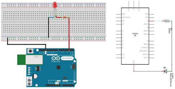
Follow the circuit diagram and hook up the components on the breadboard as shown in the image given below.
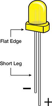
Note − To find out the polarity of an LED, look at it closely. The shorter of the two legs, towards the flat edge of the bulb indicates the negative terminal.
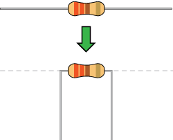
Components like resistors need to have their terminals bent into 90° angles in order to fit the breadboard sockets properly. You can also cut the terminals shorter.
Sketch
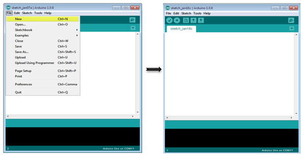
Open the Arduino IDE software on your computer. Coding in the Arduino language will control your circuit. Open the new sketch File by clicking New.
Arduino Code
/*
   Blink
   Turns on an LED on for one second, then off for one second, repeatedly.
*/

// the setup function runs once when you press reset or power the board

void setup() {  // initialize digital pin 13 as an output.
   pinMode(2, OUTPUT);
}

// the loop function runs over and over again forever

void loop() {
   digitalWrite(2, HIGH); // turn the LED on (HIGH is the voltage level)
   delay(1000); // wait for a second
   digitalWrite(2, LOW); // turn the LED off by making the voltage LOW
   delay(1000); // wait for a second
}
Code to Note
pinMode(2, OUTPUT) − Before you can use one of Arduino’s pins, you need to tell Arduino Uno R3 whether it is an INPUT or OUTPUT. We use a built-in “function” called pinMode() to do this.
digitalWrite(2, HIGH) − When you are using a pin as an OUTPUT, you can command it to be HIGH (output 5 volts), or LOW (output 0 volts).
Result
You should see your LED turn on and off. If the required output is not seen, make sure you have assembled the circuit correctly, and verified and uploaded the code to your board.
Arduino - Ultrasonic Sensor
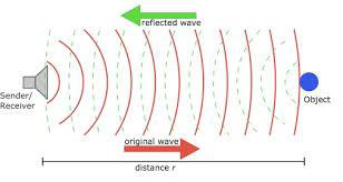
The HC-SR04 ultrasonic sensor uses SONAR to determine the distance of an object just like the bats do. It offers excellent non-contact range detection with high accuracy and stable readings in an easy-to-use package from 2 cm to 400 cm or 1” to 13 feet.
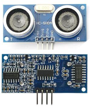
The operation is not affected by sunlight or black material, although acoustically, soft materials like cloth can be difficult to detect. It comes complete with ultrasonic transmitter and receiver module.
Technical Specifications
- Power Supply − +5V DC
- Quiescent Current − <2mA
- Working Current − 15mA
- Effectual Angle − <15°
- Ranging Distance − 2cm – 400 cm/1″ – 13ft
- Resolution − 0.3 cm
- Measuring Angle − 30 degree
Components Required
You will need the following components −
- 1 × Breadboard
- 1 × Arduino Uno R3
- 1 × ULTRASONIC Sensor (HC-SR04)
Procedure
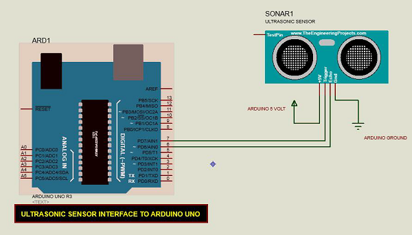
Follow the circuit diagram and make the connections as shown in the image given below.
Sketch
Open the Arduino IDE software on your computer. Coding in the Arduino language will control your circuit. Open a new sketch File by clicking New.
Arduino Code
const int pingPin = 7; // Trigger Pin of Ultrasonic Sensor
const int echoPin = 6; // Echo Pin of Ultrasonic Sensor

void setup() {
   Serial.begin(9600); // Starting Serial Terminal
}

void loop() {
   long duration, inches, cm;
   pinMode(pingPin, OUTPUT);
   digitalWrite(pingPin, LOW);
   delayMicroseconds(2);
   digitalWrite(pingPin, HIGH);
   delayMicroseconds(10);
   digitalWrite(pingPin, LOW);
   pinMode(echoPin, INPUT);
   duration = pulseIn(echoPin, HIGH);
   inches = microsecondsToInches(duration);
   cm = microsecondsToCentimeters(duration);
   Serial.print(inches);
   Serial.print("in, ");
   Serial.print(cm);
   Serial.print("cm");
   Serial.println();
   delay(100);
}

long microsecondsToInches(long microseconds) {
   return microseconds / 74 / 2;
}

long microsecondsToCentimeters(long microseconds) {
   return microseconds / 29 / 2;
}
Code to Note
The Ultrasonic sensor has four terminals - +5V, Trigger, Echo, and GND connected as follows −
- Connect the +5V pin to +5v on your Arduino board.
- Connect Trigger to digital pin 7 on your Arduino board.
- Connect Echo to digital pin 6 on your Arduino board.
- Connect GND with GND on Arduino.
In our program, we have displayed the distance measured by the sensor in inches and cm via the serial port.
Result
You will see the distance measured by sensor in inches and cm on Arduino serial monitor.
Subscribe to:
Posts (Atom)